How to Modify ELM327 to add HS/MS CAN Switch

Notice: My successful diy experience on “Add HS/MS CAN Switch” via ELM327 is only for your reference. I do not confirm all of you can test it successfully.

Most Ford and Mazda models (approximately since 2003-2004) are equipped with MS CAN Bus, while MS CAN Bus is not supported by ELM327 Bluetooth OBD2, because MS CAN is a manufacturer-specific solution and located on non-OBD2 pins.

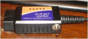
While ELM327 is a very flexible tool and slight modification allows to implement the MS CAN support. Therefore, let’s come to the process on “How to modify ELM327 in order to add the HS/MS Can switch” below:

1.5V ELM327 Scanner supports HS CAN from the stock, because Ford HS CAN completely matches to the OBD2 standard. It occupies pins 6 and 14. MS CAN bus occupies pins 3 and 11 (illustrated below).

ELM327 1

The simplest way to implement the MS CAN support is to add a switch that will shift between MS/HS CAN. The scheme below explains the modification:

ELM327 2

Roadmap:

1. Purchase a 6 pin mini-switch of ON-ON type (for example, MTS-202-A2) in any shop that sells electronic components, also prepare a wire.

ELM327 3

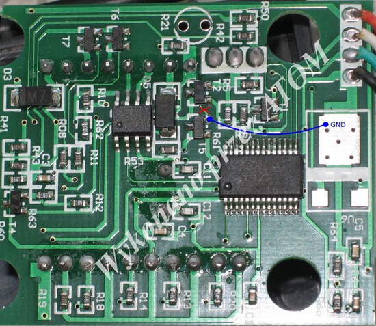
2. Disassemble ELM327 (carefully remove the label that hides 4 screws, unscrew them).

3. Find a place for mini-switch (most complex part of the whole operation for some devices that are extremely compact).

4. Unsolder wires from pins 6 and 14 of the OBD2 jack and solder them to the 2 middle pins of the mini-switch.

5. Solder 2 new wires from 2 outer mini-switch pins to pins 6 and 14 of the OBD2 jack.

6. Solder 2 other new wires from 2 other outer mini-switch pins to pins 3 and 11 of the OBD2 jack.

7. Check the work (it is very important to do not mix CAN-L and CAN-H wires up) and assembly the ELM327, mark the MS and HS can position on the device box to avoid confusion.

So far, all steps done. Hope it indeed helpful to you.

ELM327 4

Feedback about OBD2 Bluetooth with torque Pro App

One uobdii.com user buy one MINI ELM327 Interface Viecar 2.0 for Android/Window, and yesterday he shared how and what this tool can do, he think this tool is cheap and working, his professional experience and objective option will do a favor to those who never use this tool. Therefore I would like to quote his original post in the following parts.

mini-elm327-interface-viecar-20-scanner-1

I got a new toy for christmas (from me to me) and have been playing with it quite a bit lately.

First, I ordered an ODB2 to Bluetooth adapter and hooked it up. Simply pair it to your Android device (apple is more complicated) like any other Bluetooth device. I did have to restart my phone before it’d pair but my tablet paired right away. This is the one I bought:
http://www.uobdii.com/wholesale/mini-elm327-interface-viecar-obd2-bluetooth-scanner.html

the interface is highly customizable and will show TONS of parameters with the ISF ECU. I have gauges showing 0-60, 1/4 mile, speed (from ECU or GPS), Engine speed, torque, horsepower, afm, voltages, etc. It’ll also allow you to see and clear codes off the ECU. That alone was my excuse to buy it to the wife! There are different themes to the gauges, with infinite gauge layouts you can use.
I’d highly recommend this to anyone with an extra $15 lying around. The app is $4.99 and the device is $9.99.It’s a great cheap monitoring tool that I’m looking forward to using in autocross videos. It’ll do logging and everything that the more expensive tools will do for much less money. The options I mentioned are just a few of the monitor able parameters of the ECU. I’m in no way affiliated with this but I’m having a blast trying out this technology!
So far the best I’ve run is a 5.0 0-60 (tire spin in the cold).

Share with your experience about this tool with more users at:

http://www.clublexus.com/forums/is-f/765594-odb2-bluetooth-with-torque-pro-app.html

This PDF step-by-step show you how to use MINI ELM327 Interface Viecar 2.0 OBD2 Bluetooth for Android/Window:

http://www.uobdii.com/upload/pro/elm327-interface-viecar-obd2-bluetooth-scanner-user-manual.pdf

How to make ELM327 work with J1850 PWM

I got myself an Elm327 V1.5 but I found that it will not work on J1850 VPW J1850 PWM protocol especial for most Fords. But it did work like a charm on cars.

My idea came from a post in mondeoklubpolska.pl/ forum. Thanks Atom from Poland. I got the post translated into English, then I tried it out on my 2001 MK3 duratec 1.8 and it works like a charm. So I make my new version.

I have to confirm that the method only fits for elm327 V1.5 as mine and I have no responsibility if your elm327 is blow up or broken.

Equipment needs:

Screw driver

Knife

Solder iron with very small bit and solder

Multimeter

About 10 mm of insulated small-gauge wire

Then do as follows:

1) Peel off the cover of the elm327 main unit and remove the four screws by using screw driver, take these out and set the box apart.

2) Check the elm327 inside is like this

elm32714 1

3) You will notice that there is a PCB tack running between T5 and T2 there. Hook up a multimeter to check the continuity between the emitter of T5 and the emitter of T2 (on the side with two legs). If there is continuity, you should use the knife to cut between T2 and T5 as shown in red below.

elm32714 2

4) Check between the emitters of T5 and T2 to make sure there is no continuity any more.

5) Solder a short length of wire between the emitter of T5 and the emitter of T1 or Pin1 of the output connector. Be carful not to apply too much heat to T5 and T1.

elm32714 3

6) Again use the multimeter to test the continuity between T5 and Pin1 output connector. Ensure there is stable continuity.

7) Reassemble the elm327 main unit and try to test on J1850 PWM system.


The job is done.